Mechanical Speaking
Mechanical Speaking
More and more engineers are specifying mechanical splices over lap splices. They ‘ve found that mechanical splicing systems afford it reliability and consistency that can’t be found with lap splicing if you ‘ve unsure about why a mechanical splices is more desirable or which mechanical splices is best suited to next project, let us remind you of a few key point:
Mechanical Spicing
IS RELIABLE
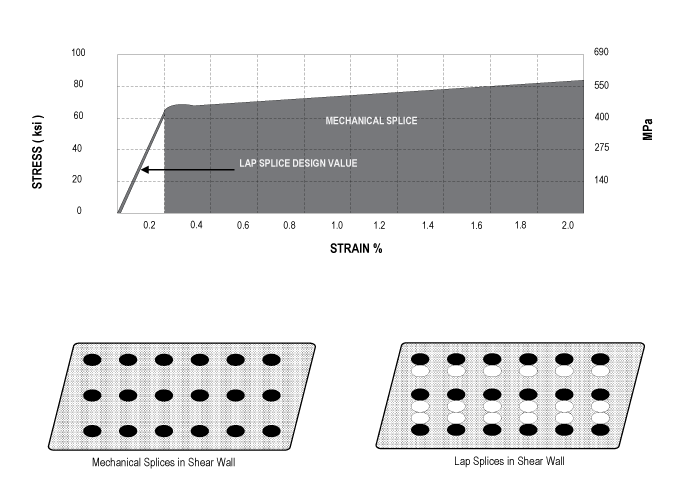
Mechanical systems are more reliable than lap systems, because they don’t depend on concrete for load transfer. Tough mechanical splicing systems maintain their consistency and durability. They offer strength and tough during manmade, seismic or other natural events.
DELIVERS GREATER STRUCTURAL INTEGRITY
ACI Requirements for mechanical splices are 1.25% higher than typical design lengths for lap splices. The strength of a mechanical splice is not affected by loss of cover caused by seismic events or corrosion. In other words, mechanical splices are
stronger than traditional lap splices – built to last and designed to perform for many years to come.
DELIVERS A CONSTENT STEEL TO CONCRETE RATIO
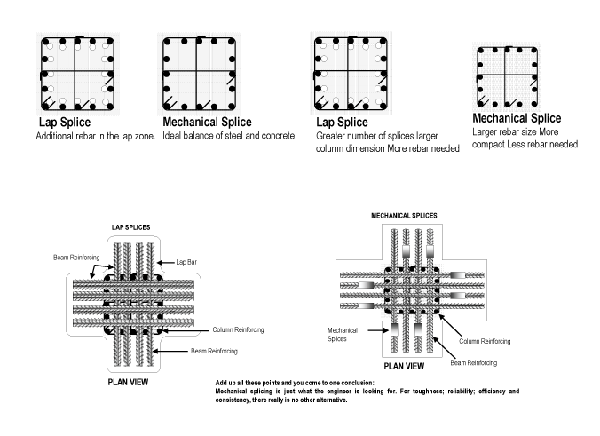
The ACI Code stipulates a steel to concrete ratio under 8%. Following this regulation and achieving a balanced design is nearly impossible with lap spicing because of the additional rebar in “ lap zone “. However a mechanical splice is designed to achieve
an ideal balance of steel and concrete by eliminating the additional rebar found in the “ lap zone” while providing greater structural integrity.
PRODUCES LESS CONGESTION
Lap splicing increases rebar congestion at the lap zone and is one of the major causes for forming rock pockets. This “strainer effect” inhibits the proper distribution of the concrete aggregate around the rebar. Mechanical splices eliminate these congestion problems and will make overall job more cost effective through minimized job site problems.
ALLOW MINIMAL COLUMN SIZING / OPTIMAL FLOOR SPACE
Working with “small “ diameter reinforcing bars may requires the use of larger column dimensions to accommodate a greater quantity of bars. Using mechanical splices allows the option of the larger diameter rebar in a smaller column while minimizing congestion. This reduced column size results in a more efficient design and an optimum use of floor space.
ELIMINATES TIME CONSUMING CALCULATION
In order to comply with current ACI Codes, designers must take tedious calculations – taking into account average centerline distances, concrete strength and location of the rebar to determine the proper length of each lap. Mechanical splicing does away
with these calculations and their potential errors while eliminating waste and unnecessary rebar costs inherent with the adoption of “worst case” calculations
IS FAST TO INSTALL
The systems require no specialized labor. In fact, an inexperienced construction crew can be trained to install mechanical splicing systems in a matter of minutes. Construction schedules ca be accelerated to optimize costs and efficiency.
IS COST EFFECTIVE
Because mechanical splices do not over lap, less rebar is used – reducing material costs. Also, the easy installation and prefabricated capabilities of mechanical splicing keeps labor costs at a minimum and jobs on schedule.
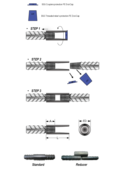
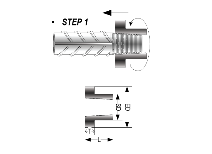
STEP 1
The coupler PE end cap is correctly fitted. Ensure the ht reinforced threaded
rebar end, couplers thread are free dirt before rotating the coupler inside the
threaded rebar. The assembly is completed by rotating the coupler to the
threaded bar until full engagement. Completed tightening requires by using 14”
pipe wrench or torque wrench to recommended torque value
STEP 2
Remove the reservation and threaded protector. Both
caps are removed.
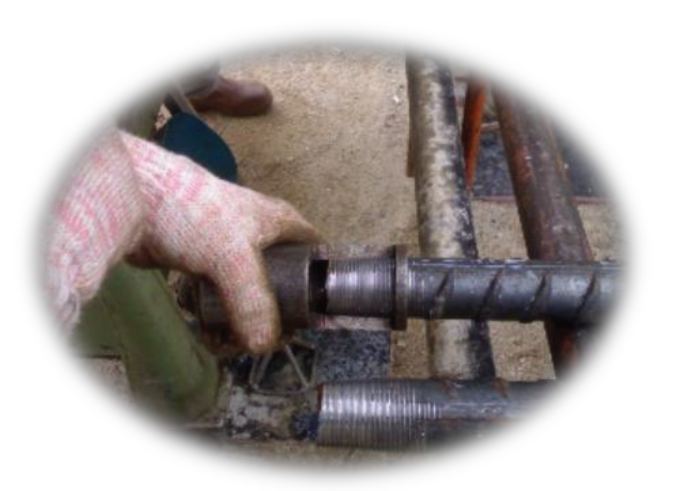
STEP 3
Ensure the both threaded portion are free concrete or grout debris.
Rotating the continuation bar until full engaged inside the coupler.
4 – 6 threaded portion of the continuation bar remains visible
outside the coupler. (is was self locking system) Completed
tightening requires by using 14” pipe wrench or torque wrench to
recommended torque value.
Practical Application of Mechanical Terminator Coupler & Mechanical Anchorage
Civil & Architectural Engineering
• Main bars of pier
• Rebar for slab shearing
• Bridge hinge
• External joint area of beam column ( main bar for beam established )
• The uppermost joint area of beam-column ( main bars for beam established )
• Main bars deep slabs
• Corner areas of the sheering wall established
• Main bar corbel established
• Rebar for wall / slab shearing
Installation Procedure
Ensure the ht reinforced threaded bar end, couplers thread are free dirt before rotating the coupler inside the threaded bar. The assembly is completed by rotating the coupler to the threaded bar until full engagement. Completed tightening requires by using 14” pipe wrench or torque wrench to recommended torque value.
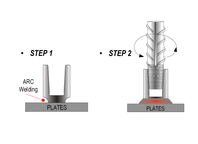
Practical Application of Mechanical Weldable Coupler
Typical Applications for Structural Connector Splices
• These coupler are mechanical from weldable grade of material such as JIS G4051 / S30C. The couplers are usually are welded to structural steel.
• A weldable couplers is welded onto steel member. The assembly is completed by rotating the continuation threaded ht reinforced bar inside the coupler until full engagement.
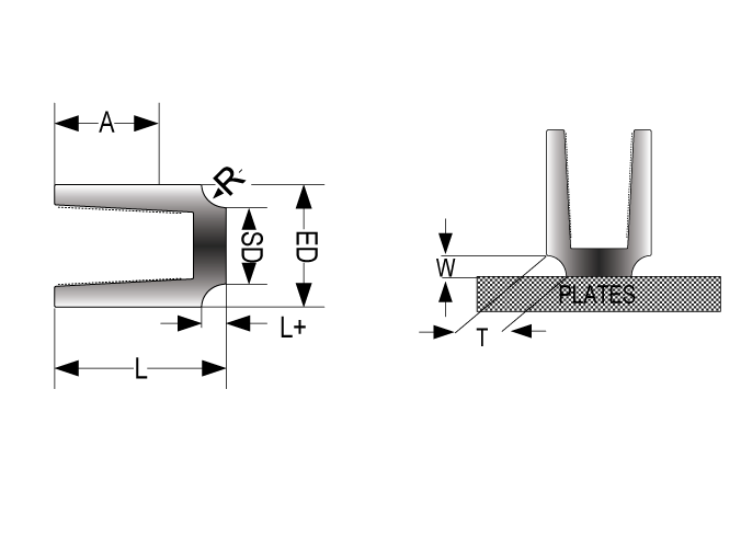
• Weldable couplers provide for connecting ht reinforced bar to structural steel section of plates. Similar to the standard type coupler, the weldable coupler is internally threaded on one end, with the other end with edge ( R ) prepared for welding.
• Welding works shall be executed by certified welders in accordance to all appropriate regulations.
Installation Procedure
Ensure the both threaded portion are free concrete or grout debris.
Rotating the continuation bar until full engaged inside
the coupler. 4 – 6 threaded portion of the continuation bar
remains visible outside the coupler. ( is was self locking system )
Completed tightening requires by using 14” pipe wrench or torque
wrench to recommended torque value.
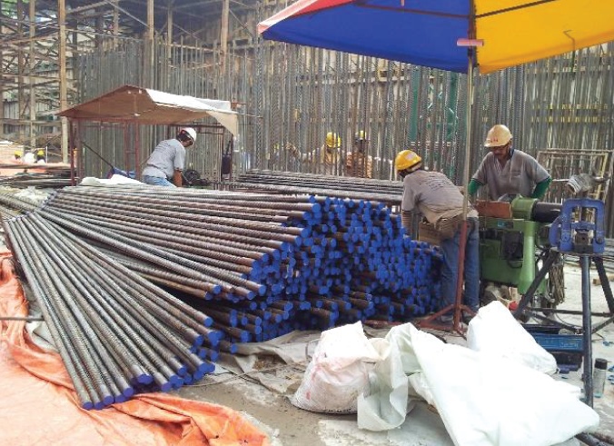
Rebar End Threading Procedure
Before any threading on the rebar is done the following step must be carry-out.
1. Check that the threading machine is in good working condition, before start work.
2. Check that the “control key” setting is the same as the reinforcing bar that need to be thread, Example : T40mm reinforcing bar setting to T40mm “control key”, and position the cutting die heads to control the thread length.
3. Slot the reinforcing bar into vise of the threading machine and tightened it tightly.
4. Switch “ON” the threading machine and move the cutting die heads toward the reinforcing bar and “THREAD” it.
5. When threading on the reinforcing bar is completed, the cutting die heads will automatically self opening, stop to move forward. Manually closed.
6. Move back the cutting die heads to it original position, released the vise and take out the completed threaded reinforcing bar.
7. Use a “QC” gauge to check on the quality of the threaded end of the reinforcing bar, to ensure perfect fit and good enough length, If it is “OK” will be continue on the next piece of the reinforcing bar until the tenth (10) piece.
8. When threading end on the tenth (10) piece of reinforcing bar is completed, a “QC” gauge will be use to check on the quality of the reinforcing bar threaded end.
9. Procedures number “7” will be use for “QC” checking after every tenth (10) piece until all reinforcing bar threading end are completed.
The technical parameter for the tapered cut threaded machine
• The whole weight of the machine = 210kg
• The power of the electric main motor = 5HP / 3Phase x 415Volts
• The power of the electric water pump motor = 1/8HP x 3/8PT x 3 Phase x 415 Volts
• Output rotate speed of reducer = 60R.P.M.
• Outer dimension = 850mm (L) x 330mm (W) x 1020mm (H)
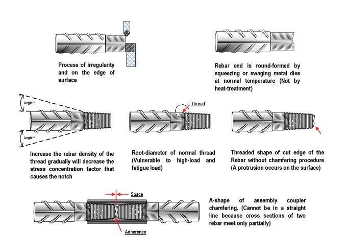
Example of Protruding Threaded

1. Rebars section from factory

2. Rebars end squeezing & swaging process

3. Rebars edge and surface processing

4. Cut the threads by specially designed degreed chaser